By: Fred Grenning, The Hose Monster Company
The purpose of this document is to present a case for modifying NFPA and AWWA standards related to Fire Flow Testing of Hydrants so that identifying inoperative hydrants and inadequate water supplies can be done in the most efficient and economical way. The principal purpose of fire flow testing is to verify available water and identify possible deficiencies in the hydrant system. With this purpose in mind I believe that a fire hydrant capacity test, where every hydrant is flow tested, should be performed rather than the current recommendation of a main capacity test where not all hydrants are flow tested, and therefore non-flow tested hydrants that are deficient may not be properly identified.
It is not uncommon for a fire department to respond to a fire with millions of dollars of apparatus and ready and able firefighters only to find that the hydrant doesn’t work. The result being loss of life and property. (see Hydrants did not work; evidence.docx)
How can this happen?
The answers are any of one or more of the following:
- The hydrant components fused together from non-use.
- Hydrant stem breaks.
- The hydrant was vandalized.
- There was maintenance on the water system and valves were closed but never reopened.
- The piping system tuberculated.
- The hydrant was exposed to water freezing in the barrel.
These are some of the many possible reasons for a hydrant being unable to provide water for the fire department in an emergency.
When firefighters respond to an alarm they expect the hydrants to work. How can it be known that a hydrant will open when needed and has the flow-rate capacity to fight a fire? The answer is to operate every hydrant and evaluate the water supply at the hydrant nozzle where the fire department is going to connect.
The NFPA 291 recommends a flow test that partially addresses this issue the Fire Main Capacity Flow Test. There is another test that is better designed for this purpose. The Hydrant Capacity Fire Flow Test, which more accurately predicts water available from a hydrant and is more economical to perform.
The Fire Main Capacity Flow Test is the test recommended by both NFPA 291 and AWWA M17. This test determines the value of the water supply of the underground fire main at the location of the fire hydrant.
The Hydrant Capacity Fire Flow Test determines the value of the water supply at the hydrant nozzle where firefighters are going to connect their suction hose. This procedure also determines whether the hydrant is mechanically functioning properly or not. The information derived from this test can be used by the fire service to plan for fighting fires.
The hydrant capacity flow test is not included in either NFPA 291, Recommended Practice for Fire Flow Testing and Marking of Hydrants, or AWWA M17, Installation, Field Testing, and Maintenance of Fire Hydrants.
Both tests are valuable, and correct or incorrect depending on the purpose of the test. If a fire sprinkler contractor needs to know the capacity of the water supply to hydraulically calculate a sprinkler system the Fire Main Capacity Flow Test is the correct test. If a firefighter needs to know that the hydrant works and the capacity of that fire hydrant, then the Hydrant Capacity Fire Flow Test is correct.
What is the difference?
Comparison of Hydrant Capacity and Main Capacity Flow Tests
| Hydrant Capacity Test | Fire Main Capacity Test | |
| Number of Hydrants | 1 | 2 or more |
| Water Flow Capacity is measured at | Test Hydrant | Underground main |
| Verifies Mechanical Operation of Test Hydrant | Yes | No, only the flow hydrant |
| Verifies the operation of the valves and piping that provide water to the Test Hydrant | Yes | No, only the flow hydrant |
Limitations of the Fire Main Capacity Flow Test
- The Main Capacity flow test overstates the flow-rate capacity that firefighters will encounter when they connect to the hydrant because this test does not hydraulically measure friction loss in the piping between the underground main and the test hydrant.
- The Fire Main Capacity flow test does not verify the functionality of the Test Hydrant because the only use of the Test Hydrant is to measure static and residual pressures. The Test Hydrant in this test never flows water.
- The Fire Main Capacity test does not verify the functionality of the connection between the underground main and the hydrant because the Test Hydrant never flows water. A test could be done on as described in either NFPA 291 or AWWA M17and an auxiliary valve that was left 95% closed would not be detected.
For the purposes of determining and indicating the available fire service water and identifying possible deficiencies in the hydrant system the Hydrant Capacity Fire Flow Test is most appropriate. It verifies that the system works from the water source all the way to the hydrant. It is from the hydrant that the firefighters count on getting water to extinguish fires. In addition, this test requires less manpower, which makes it less expensive to perform and therefore more likely to be performed.
It is good practice to conduct flow tests on all parts of the distribution system, periodically and on demand, to identify the service areas affected by significant changes in the distribution system.
NFPA 291 recommends five years. AWWA-M17 suggests ten years. Why five years or ten years? There is always the potential that an aux valve could remain partially closed and forgotten any time work is done on the system. Hydrants and valves should be on a schedule of once per year and following any maintenance on the system in the area.
In summary, the goal of NFPA 291 and AWWA M17 is to provide guidance for those whose job it is to determine available water supply and to identify deficiencies. The Hydrant Capacity flow test would accomplish this better than the Fire Main Capacity Test. Both publications should be modified to define and include both procedures and their respective application.
TERMS USED IN FLOW TESTING
Residual Hydrant is referred to, but not defined.
My recommendation is to define the following:
Residual Hydrant – (also known as Test Hydrant) this hydrant is located at the Hydraulic Point in the system that is being evaluated. The static and residual readings are taken from a gauge cap on this hydrant.
Hydraulic Point –
- in a Hydrant Capacity Fire Flow Test, the Hydraulic Point is located at the gauge cap
- in a Fire Main Capacity Flow Test, the Hydraulic Point is located in the fire main close to the hydrant.
Hydrant Capacity Fire Flow Test (also known as Single-hydrant test)
The Hydrant Capacity Fire Flow Test evaluates the water supply available from the hydrant. The information derived from this test is used by the fire service to plan for fighting fires. If all hydrants in a system are tested, partially closed valves and other obstructions will become known. This test uses a single hydrant as both the Residual hydrant and the Flow hydrant.
Fire Main Capacity Flow Test
A Fire Main Capacity Flow Test evaluates the water supply of the fire main at the location of the test hydrant. The information derived from this test is used by city planners and contractors to consider the water supply for general use and fire sprinkler systems.
Recommendations to NFPA 291 committee members
Regarding figure 4.7.1 Outlet-nozzle coefficients from NFPA 291 2013 Edition
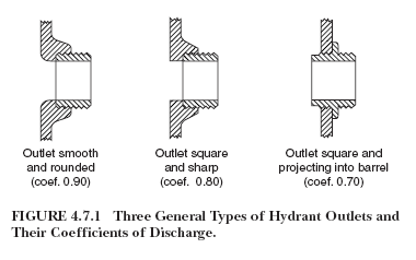
The coefficients listed next to the nozzle shapes in Figure 6-3 are not known to be verified by any independent testing laboratory. For the last 20 years my business focus has been providing fire flow testing solutions. I have never found the source for the coefficients applied to the three different nozzle shapes. Nor have I encountered any person who knows of a hydrant nozzle being of the shape indicated in figure 6-3-C.
New Terms:
Residual Hydrant or Test Hydrant: The hydrant that is being reported on.
Test Flow: Flow-rate measured from the Flow Hydrant used in determining Desired Flow
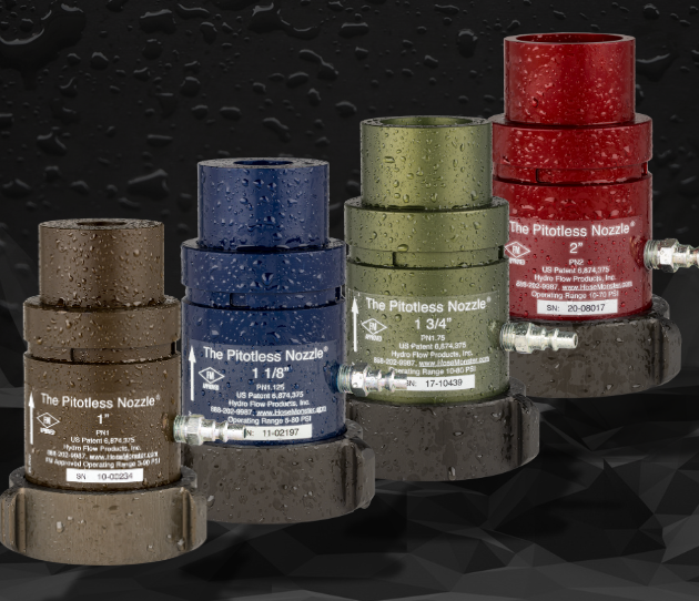
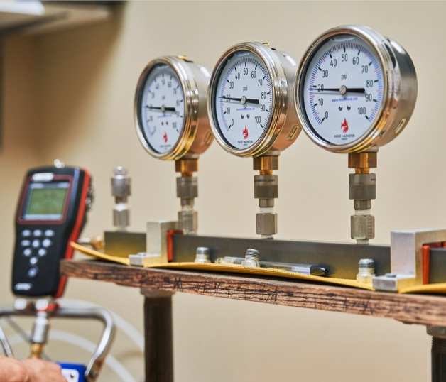
Nozzle Pressure: Pressure reading from a pitotless type nozzle used to calculate flow-rate. Note that Nozzle Pressure is not generic and is specific to an Approved nozzle. Conversion tables are supplied by the manufacturers of this type of nozzle.
K-factor: The constant used to convert pitot pressure or nozzle pressure to flow-rate. (Q = k * P^.5)